

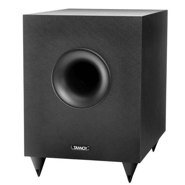
Tannoy SFX5.1 Sub Woofer Repair
I have a Tannoy SFX5.1 Sub Woofer which, by design, only "powers up" when an audio input signal is detected. To enable this operation there's an internal +/- 12 Volt power supply which is permanently in the on state.
A little while ago my sub-woofer, while in stand-by, started to randomly make noises like distant thunder - also, it wouldn't power up. I "googled" the symptoms, and discovered that I wasn't alone in experiencing this problem - the exact fault (in the stand-by power supply) is described in an excellent blog, and some youtube videos.
I followed the instructions in Andy Doswell's Doz' Blog, which enabled me to repair the fault by replacing a couple of transistors (C1815/NPN A1015/PNP) on the power supply board. At the same time I tested the electrolytic capacitors - a few had failed, so I replaced them all.
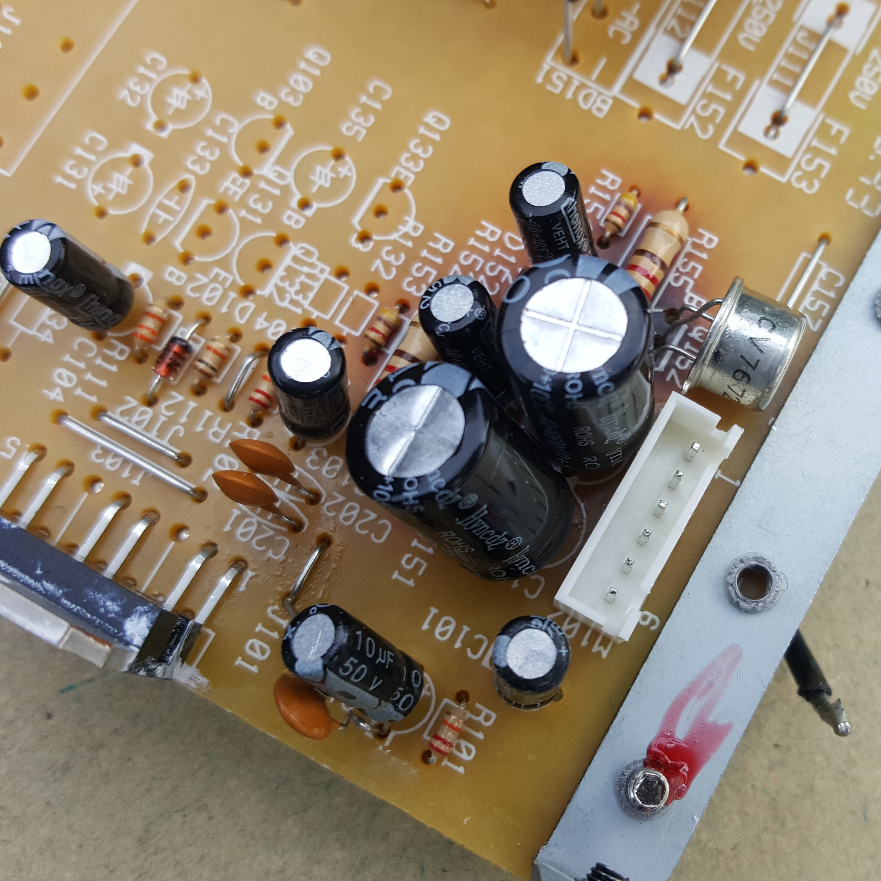
After the repair all worked OK for about a week, then the fault reoccured. This time it was just the -12volt supply not working - the A1015 (Q152) transistor had blown, so I replaced it with a CV7672 (equivalent to 2N2905A), which has a higher voltage/current specification and a max collector power dissipation of 600mW. Note that it also has a different pin configuration.
UPDATE: Since I performed the repair I see that PeterCB, a contributor to the Doz' Blog, has had success in replacing Q151 with a with a TIP31 and Q152 with a TIP32 - see the blog. These transistors can dissipate 2 Watts (without a heatsink), so should only just get warm in this application.
For the last five months my Tannoy Woofer has worked without a problem - I keep it in stand-by 24/7.
Some Things to Note
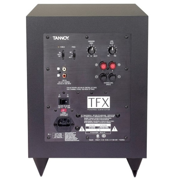
- To avoid cosmetic damage, don't try and prise the back panel off the woofer - instead, remove the speaker from the base and push the back panel off from inside.
- Don't believe everything in the youtube videos - the failing circuit is a pair of zener controlled transistor series voltage regulators (not a "class AB push pull amplifier")
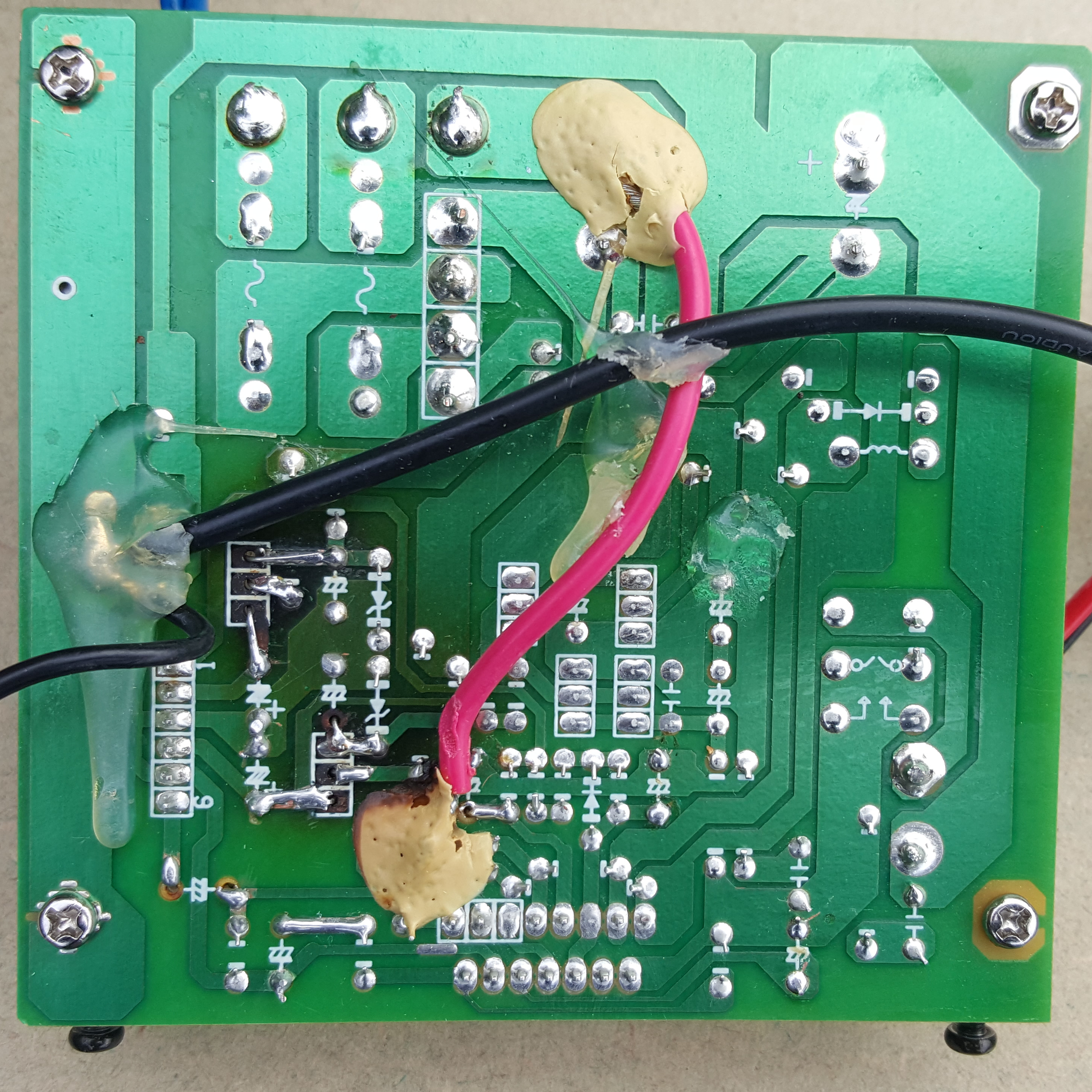
- The tracks on the pcb are thin and very fragile, it is virtually impossible to remove components without lifting some of the track, so be prepared to do some rework to maintain the circuit.
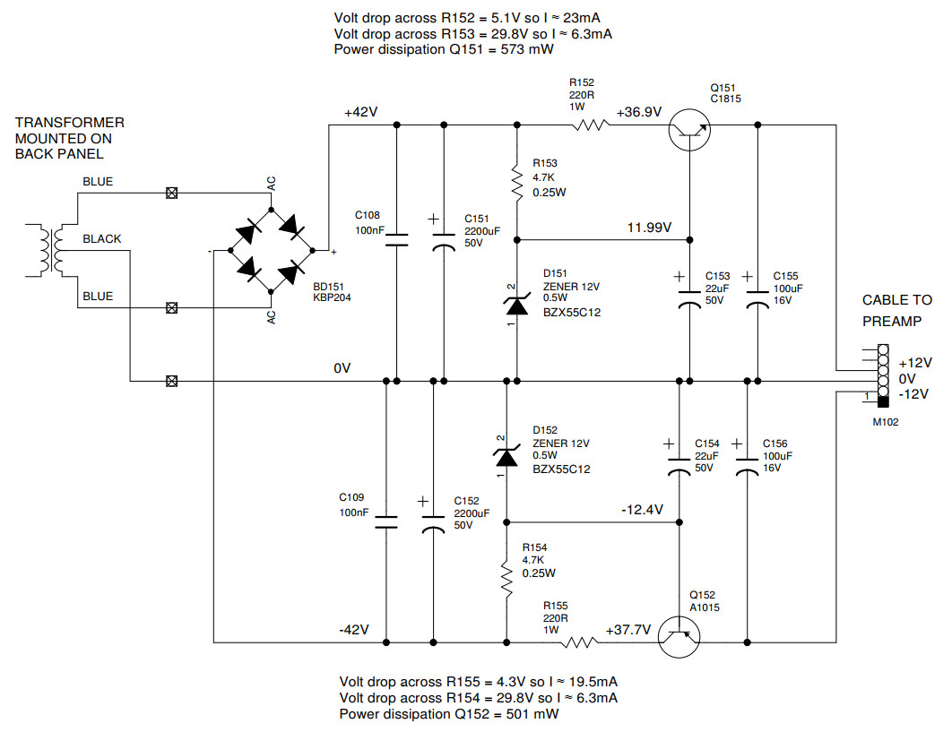
- Q151 and Q152 replacements: These BJT's run very hot because (from measurements) they are dissipating approx. 573mW (Q151) and 501mW (Q152) - this is close to, or exceeds, the component manufacturer's maximum ratings. Datasheets from various manufacturers of these transistors give the max "collector power dissipation" in the range 300mW to 625mW, so if replacing components with the same/similar part number, it's important to know the actual specification of the component - don't just rely on a part number!
Circuit Diagram for Tannoy SFX5.1 Sub Woofer Power Supply
I couldn't find a circuit diagram online, so I drafted one - you can download/print it here. As a bonus, I've included component values and some voltage/current readings that might be useful.
Let me know of any errors, or suggested improvements, via the Contact Us form on this site.
Last Modified: Tuesday 29th June 2021 at 07:03 UTC